In the 1830s, Michael Faraday’s experiment involving the coupling of electricity and magnetism had shown a definitive relationship and resulted in creating a time-varying magnetic field. The coil of a wire attached to the galvanometer acted as a loop antenna and received the electromagnetic radiation which was detected by the galvanometer. Then, Heinrich Hertz came up with ideas to develop a wireless communication system in which an electrical spark occurred in the gap of a dipole antenna in 1886. There are many current research on antennas involving metamaterials that have engineered dielectric and magnetic constant. For example, some might focus on building smaller antennas that will be useful for personal wireless communication devices like cell phones. Hence, lots of work must be done on the numerical modeling of antennas so that their properties can be predicted by doing the simulation before they are built and tested.
The antenna is the transitional structure between free space and the guiding device, as shown in Figure 1. The antenna receives an electric signal and radiates it as an electromagnetic wave and vice versa. It is advisable to use a closed conductor along with the help of the principle of electromagnetic induction that enabled us to produce a fluctuating magnetic field and electric field around it. The electromagnetic wave must be separated from its source. Hence, the propagation of the wavefront makes an appearance. It is interesting to know that the wavelength of the propagation produced is exactly double of the length the dipole. In other words, the antenna acts as a transducer that transmits or receives electromagnetic waves. There are two types of patch antenna that are widely used which are rectangular and circular patch antenna. Furthermore, in the advanced wireless system, the antenna is required to be optimized and accentuate the radiation energy in some directions and suppress it in others.
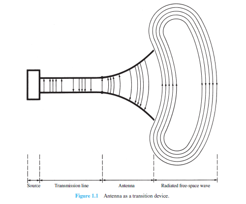
Figure 1 Antenna as a transition device
(Source: Antenna Theory: Analysis and Design)
Nowadays, antennas are one of the advanced technologies that have become ubiquitous for civilian and military purposes as it was first introduced in 1950. Later, for about 20 years this technology had been improvised into printed circuit board (PCB) technology and they are becoming more popular in the industry as they can be easily printed onto the circuit board. Microstrip patch antenna comes with a wide range of applications due to its lightweight, low profile, low cost, planar configuration, ease of conformal, superior portability, suitable for the array with the ease of fabrication and integration with microwave monolithic integrated circuit (MMIC). Microstrip patch antenna has many applications such as radio-frequency identification (RFID), broadcast radio, mobile system, a global positioning system (GPS), television, multiple-input multiple-output (MIMO) system, vehicle collision avoidance system, satellite communication, surveillance system, remote sensing, missile guidance and so on.
There are many types of active elements that can be used to produce thick film paste. For example, conductive materials consist of silver, carbon nanotube (CNT), resistive such as carbon, insulative such as ceramic, and magnetic which consist of ferrite. Each type of active element requires a specific weight ratio depends on its density. For organic vehicles, linseed stand oil is used as the main ingredient due to its ability to polymerize even at room temperature. Linseed stand oil is suitable to use for lower firing temperatures and has higher viscosity compared to raw linseed oil. The organic vehicle was first prepared by mixing linseed stand oil with m-xylene and - terpineol using a magnetic stirrer and ultrasonication process after a few hours to obtain homogeneity. Next, nanopowders such as CNTs are added to the organic vehicles by using the ultrasonication process. The conductive and microstrip feed line was then screen-printed onto the substrate, dried, and fired at high temperatures. Finally, the thick film patch antenna is ready to be observed and measured using a vector network analyzer.
To conclude, the technological advancement of the microstrip patch antenna is increasing day by day. A lot of research work is still in progress for its better utilization in the future. Furthermore, many techniques are coming into existence by compensating the gain and the bandwidth of the microstrip patch antenna. Hence, learning a little or a large amount about antenna could not hurt since its known contributions to one’s overall understanding of the modern world.
References:
Balanis, C. A. (2016). Antenna Theory: Analysis and Design. John Wiley & Sons, Inc.
Microstrip patch antennas: An historical perspective of the development. (2011). Retrieved from Institute of Electrical and Electronic Engineers (IEEE): Microstrip patch antennas: An historical perspective of the development
By: Hamizahtul Nurul 'Izzah Binti Zainuddin, Internship Student, Functional Devices Laboratory, Institute of Advanced Technology (ITMA), UPM.
For further information, please contact:
Dr. Intan Helina Hasan
Research Officer
Functional Devices Laboratory (FDL)
Institute of Advanced Technology, UPM
i_helina@upm.edu.my
Date of Input: 29/06/2022 | Updated: 29/06/2022 | roslina_ar
MEDIA SHARING